Welcome to the Minverter Project
-
GATT isn't just a trade agreement: creating a custom BLE Service
The upside of selecting a widely used protocol, like BLE, is that there is a great deal of information and infrastructure surrounding it. The downside is that there is a great deal of information and infrastructure surrounding it. Some of this complexity is inherent, some is due to accomodating many divergent use cases, and some is just accumulated cruft, but all of it needs to be dealt with.
-
Correct use of the Zephyr system workqueue, aka multiprogramming is fun
Last time I mentioned an issue with the output sometimes getting “stuck” rather than being turned off correctly. Having a good understanding of how and when things happen in the control system is important, particularly if what is being controlled is safety critical. And power conversion equipment is. So what was happening?
-
Wireless control using BLE
A microinverter (or almost any piece of equipment) needs an interface to monitor and control its state. There are many ways this can be done: buttons and dials on the front panel, a separate wired port using some protocol, power line communication using the wired connections you already need, or radio. There are lots of advantages of RF communication: no physical connection needed, so you can cross walls and avoid wiring rat’s nests; lots of bandwidth available; many many standards and low cost implementations available. There is a concern with interference from other RF sources, but we as a society have spent more than a century managing the issue. And not needing buttons on a front panel, and using the phone that everyone is carrying anyway, seems like a win. So let’s see if that can work.
-
Asynchronous PWM
Something you might have noticed about the PWM code I posted is that the sinusoidal waveform is generated by a busy-wait loop in the main function. It sets the PWM to the right level, sleeps, then does it again. This is fine for a demo, but obviously inappropriate if the controller needs to be doing other things at the same time: communications, measurements, calculations, receiving and processing user commands, anything. Zephyr, being a thorough RTOS, has excellent support for asynchronous stuff. For instance, using a timer to update the PWM would be an improvement. Let’s do that:
-
Changing PWM pulse lengths
So what caused the glitch we saw?
-
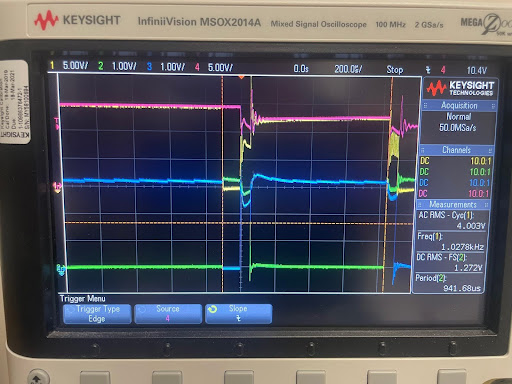
Glitch!
Uh oh! What could cause this?
-
AC signal analysis
With the ability to take data in hand, we need the capability of analyzing it, and determine both AC and DC characteristics of the signals.
-
It looks stupid and I feel stupid


Here is a test assembly.
-
Frick
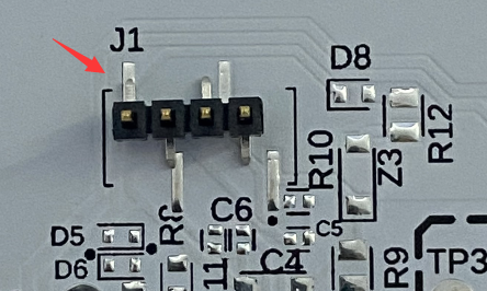
One of the joys of working with hardware is that you get to make decisions that have consequences.
-
Half bridge prototype ordered
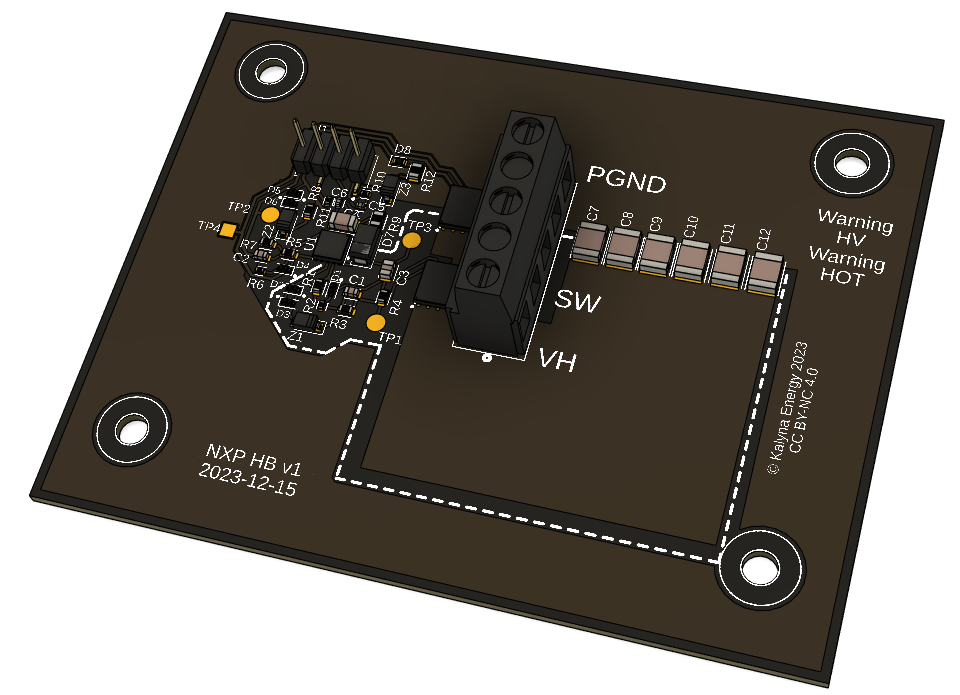
So I successfully finalized the layout and placed an order. It’ll look something like this:
-
Power output connector
I revised the location of the output caps, and felt comfortable enough to get the board and parts list quoted. The vendor said could use resin in the power connection pads to insulate from the IMS board, but at an added cost. We’re not trying to optimize for cost of prototypes, just the eventual product, but still. Also perhaps those pads wouldn’t be the easiest to use anyway. An alternative might be to use a terminal block, like this TE 282843-3 Eurostyle screw terminal.

-
Bypass capacitors
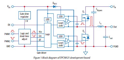
Here’s the EPC90121 block diagram, showing onboard power bypass capacitors.
-
Gate drive layout
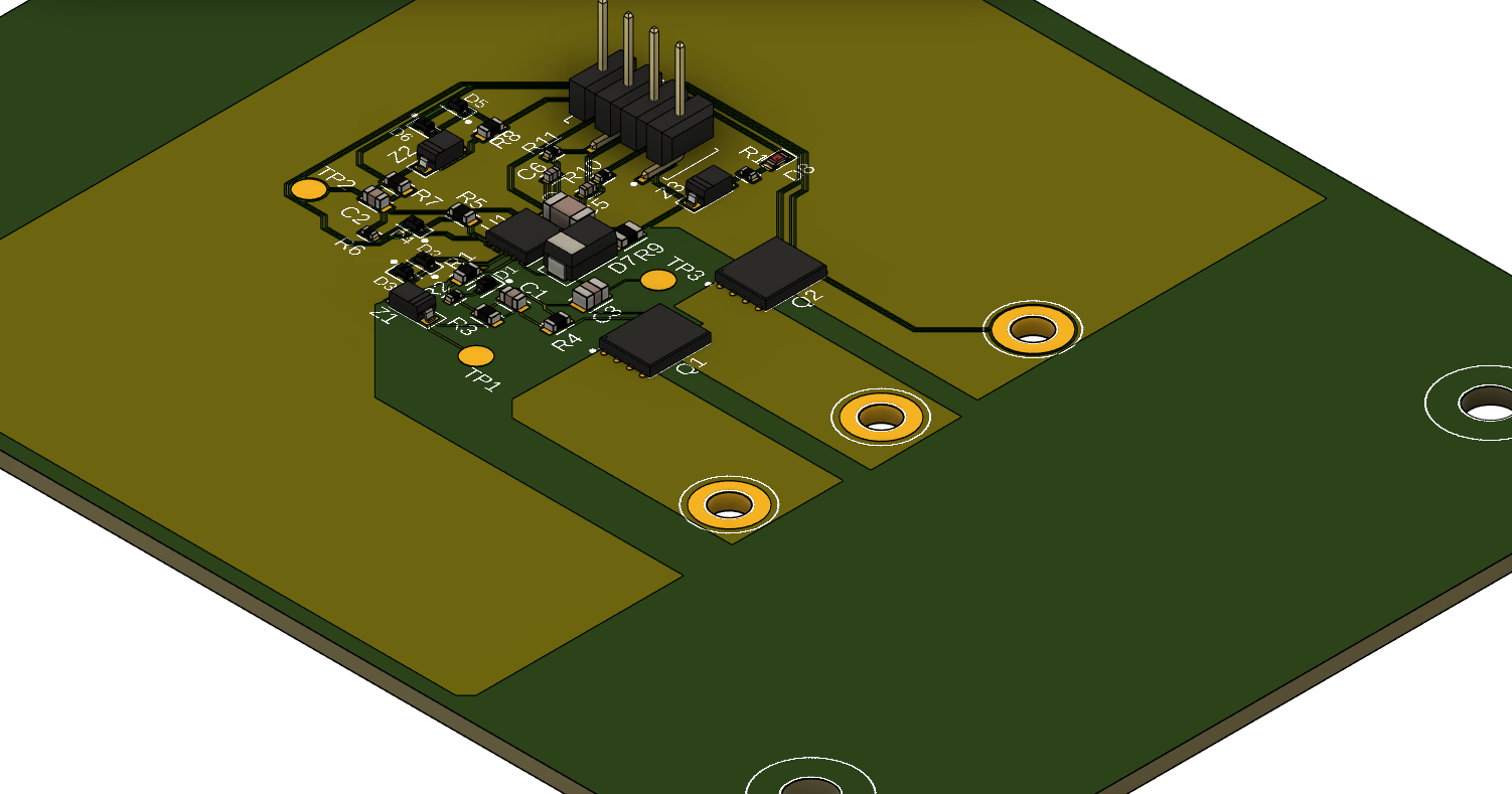
As it turns out, the software will spit out a full render of the entire circuit, with traces and packages for all the components, assuming you have packages for the components you are using.
-
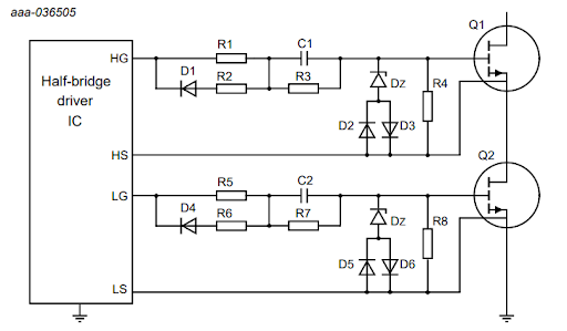
Gate drive layout
The actual gate drive is a litte more complicated than in my test layout. I’m using the circuit from AN90041, which looks like this:
-
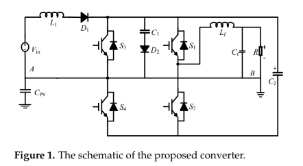
A four switch boost inverter?
Awhile back I came across the following inverter topology:
-
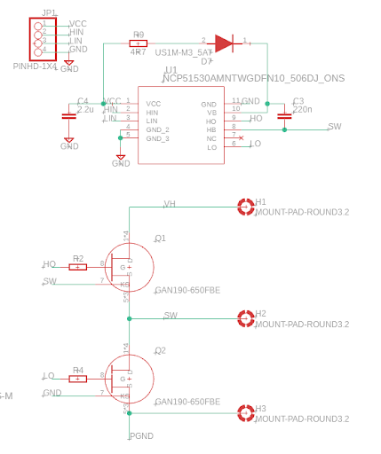
Single layer test layout
A reasonable question after picking a whole bunch of appealing design rules is whether you’ve argued yourself into an unfeasible position. Single layer is a strong constraint. I note that the Nexperia sample PCB is certainly not single layer, nor is the sample layout in the NCP51530 data sheet. Single layer layouts can be a little complex, global geometry optimization problems. However, you have lots of components which can kind of act like jumpers to put a trace under, and flexibility as to where you put connectors, etc. You can add more zero resistance resistors if you need more jumpers, too. We also need to meet voltage clearance constraints, plus all the other requirements and recommendations for the circuit. I figured it’d be a good idea to try a test layout of a simplified version just to see if the rules were already too restrictive.
-
PCB layout rules
While doing the layout, one must determine what manufacturing constraints are present. These will be some combination of technically feasible, economically feasible, and technically required.
For this project, I’m hoping to use an aluminum core PCB. Reasoning: mechanically strong and stiff, so it might form part of (or all!) of the product housing. Conductive, so can form part of (or all!) EMC shielding. Highly thermally conductive, so can help reduce (or eliminate!) the need for other heat sinks. Lots of expectations here.
-
Limitations of nonisolation
So what could we do with this half-bridge board, once it’s done, assuming it works? Well, build a lot of power conversion circuits. Here are a few examples:

Basic buck DC-DC converter. The upper switch on the high side does PWM, there’s an inductor on the switch node to average the current, and the low side switch could be a passive diode or actively switched to reduce resistance.

Here’s a boost converter. Now the inductor is on the input side, connected to the switch node. The high side switch is acting as a diode, and the low side is doing PWM.
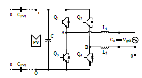
Here’s a full bridge inverter, from two half bridges connected in parallel. The two output terminals are connected to the switch nodes of the indivudal half bridges, allowing current to flow either direction depending on the switch states.
How about other inverter topologies? Here’s a transformerless example from the literature, using a common ground between the input and output to eliminate common mode ground current, with a flying capacitor to enable the negative cycle.
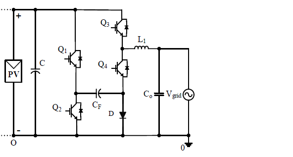
This looks like two half bridges plus a diode, so it looks fine. However, there’s an issue. In order to support negative currents, the low side of the Q3-Q4 pair must be connected to a node which is below the common ground potential. The issue is how to drive the gates. A gate driver like the NCP51530 will let the switch node and the high gate float up, using a diode charging a cap to provide the high side gate voltage, but this won’t work if the low side is going below ground. Note the supply VCC and the logic inputs LIN and HIN are all referenced against the same ground as the low side gate voltage. This gate driver simply can’t work for Q3 and Q4 in this circuit, if connected to the common ground.
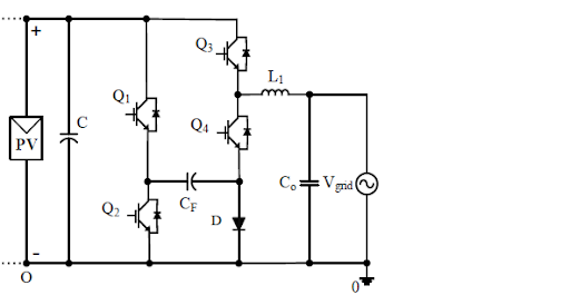
The solution is a fully isolated driver. Here’s how one might get hooked up:
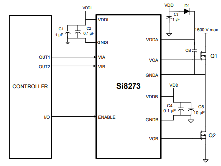
Note the separate grounds and separate power supplies for the input and output sides. Where you get that floating side power is your problem. There are solutions for that too, like this integrated transformer converter. But it’s a problem that has to be solved to control a gate which floats below ground.
-
Board design
It’ll be hard to do anything without the capability of making useful schematics and board layouts. I’m using Fusion 360, a reasonbly nice commercial CAD system, the electronics part of which grew out of Eagle. It’s been awhile, and they are constantly updating and changing things, so I figured I’d go through a tutorial while working up a simple board. I picked building a half bridge driver board for the Nexperia GAN190-650FBE GaN transistor, because these are new and interesting devices for which dev boards are not available.
-
ADC front end
Now that we’ve tried out the onboard ADC, we need to talk about how to make it useful, ie how exactly to connect the signals of interest to the measurement input. We can’t just tie it directly, we’ll want to deal with signals up to hundreds of volts, and the analog input pins can’t take anything outside of 0 to Vdd=3.3V without frying.
-
Analog-digital conversion
To interact with the world, the inverter will need to be able to measure voltages and currents at its inputs and outputs, as well as internal state. This is the realm of analog-digital conversion. Because this need is so ubiquitous, many microcontrollers have some capability built-in. The nRF52840 has a successive approximation ADC peripheral, documentation here. Its specs are reasonable: 8 single ended channels, 200 ksps overall sample rate, 12 bit resolution (14 with oversampling), 9 bits effective after noise and distortion. Much fancier units exist, but this is already there, on the chip. Maybe it’ll be good enough.
-
Setting up a console
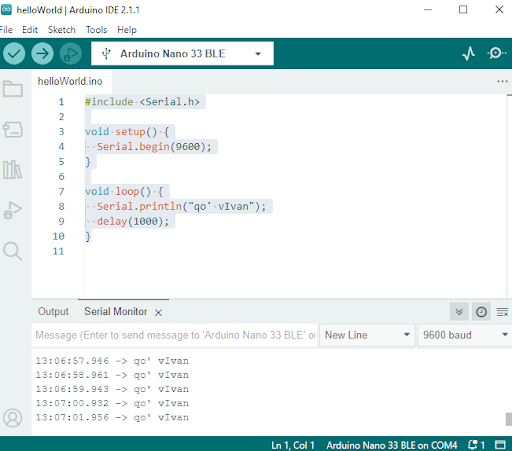
You can do a lot of debugging with just an LED, but many things become easier if your program can print things for the developer to see. Y’know, hello world. The Arduino universe makes sure that this code is pretty easy to write, program, and see the output of:
#include <Serial.h>

void setup() {
  Serial.begin(9600);
}

void loop() {
  Serial.println("qo' vIvan");
  delay(1000);
}
-
Hardware PWM
Essentially every switched mode power converter uses pulse width modulation somewhere, plus large quantities of other applications, so it is not surprising that control hardware frequently supports PWM. This means we don’t need to be manually toggling pins under software control, like we did earlier, which clutters the code, makes the CPU unavailable for other uses, and potentially doesn’t allow the same performance as the hardware. The nRF52840 has a full featured PWM peripheral, but how do we use it?
-
Approximating a sine wave without sin()
If we want to make a sinusoidal signal, we need a sine wave. sin() is part of the standard C math library, but unfortunately this is not trivially available on all microcontrollers. I went looking for a suitable approximation, and there is a truly ancient one: Bhāskara I’s sine approximation formula, dated to 7th century CE.
-
A simple inverter
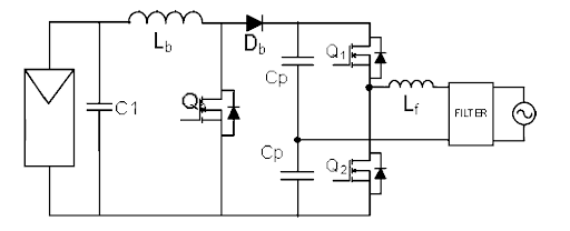
It’s possible to make an inverter with nothing more than a pair of caps and a half-bridge. Here’s a circuit:
-
Toggling a pin
Suppose we want to control something, with a microcontroller. We need to create some type of output. Microcontrollers are set up so that you can use their pins for general purpose I/O.
-
Project update
So I’m coming back to this project after a somewhat extended hiatus.
-
Related projects
Projects / products
- Poida MPPT controller
- OzInverter
- OpenInverter Aimed at DIY EVs and motor control
- Libre Solar Open hardware and software for DC energy systems
- OSI Rectifier/inverter, aimed at small wind
- OSSI
- arshmah inverter small, based on CD047 monostable multivibrator. A related inverter design
- 1 kW MPPT charge controller Can purchase from link
- EG Micro 1kW inverter Based on their EG8025 single phase SPWM controller chip
Reference designs from vendors
- PMP9461 TI reference design for isolated 165W inverter, with schematics, BOM, layouts, detailed technical docs. Others from TI: 1, 2
- 3.5 kW inverter design from Transphorm. FB, C2000 control, Si823x gate drivers, current and voltage sense on output. Now discontinued, new 3 kW one uses dsPIC33 controller.
-
PV benefit
The right metric for where to install solar
The world has a limited capacity for producing new PV modules. Where’s the best place to put them?
-
Project goal
Project Goals: Developing Affordable Microinverters
The focus of this project is the design and development of a open source low-power DC to bipolar AC microinverter.