Limitations of nonisolation
So what could we do with this half-bridge board, once it’s done, assuming it works? Well, build a lot of power conversion circuits. Here are a few examples:

Basic buck DC-DC converter. The upper switch on the high side does PWM, there’s an inductor on the switch node to average the current, and the low side switch could be a passive diode or actively switched to reduce resistance.

Here’s a boost converter. Now the inductor is on the input side, connected to the switch node. The high side switch is acting as a diode, and the low side is doing PWM.

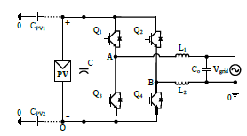
Here’s a full bridge inverter, from two half bridges connected in parallel. The two output terminals are connected to the switch nodes of the indivudal half bridges, allowing current to flow either direction depending on the switch states.
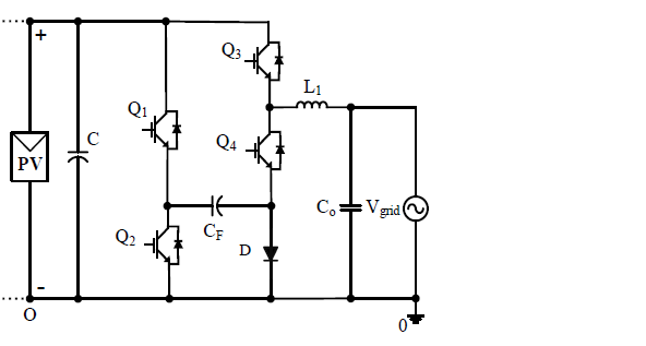
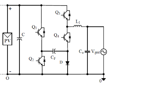
How about other inverter topologies? Here’s a transformerless example from the literature, using a common ground between the input and output to eliminate common mode ground current, with a flying capacitor to enable the negative cycle.

This looks like two half bridges plus a diode, so it looks fine. However, there’s an issue. In order to support negative currents, the low side of the Q3-Q4 pair must be connected to a node which is below the common ground potential. The issue is how to drive the gates. A gate driver like the NCP51530 will let the switch node and the high gate float up, using a diode charging a cap to provide the high side gate voltage, but this won’t work if the low side is going below ground. Note the supply VCC and the logic inputs LIN and HIN are all referenced against the same ground as the low side gate voltage. This gate driver simply can’t work for Q3 and Q4 in this circuit, if connected to the common ground.

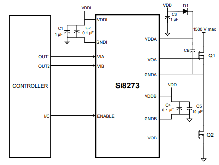
The solution is a fully isolated driver. Here’s how one might get hooked up:

Note the separate grounds and separate power supplies for the input and output sides. Where you get that floating side power is your problem. There are solutions for that too, like this integrated transformer converter. But it’s a problem that has to be solved to control a gate which floats below ground.