Glitch!
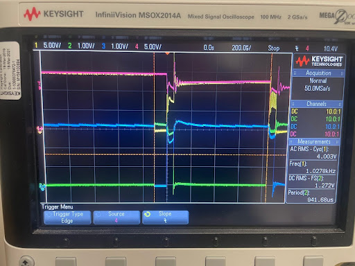
Uh oh! What could cause this?

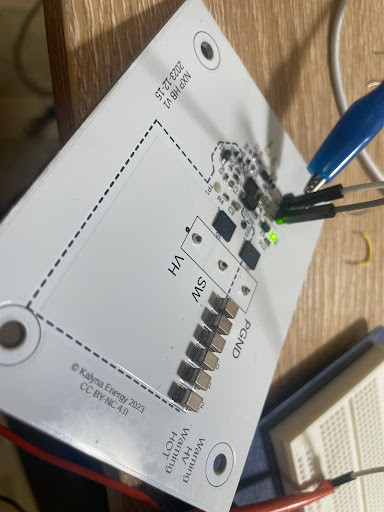
Okay, let’s back up. First of all, yes the boards did arrive. This is what they look like:

and they do turn the LED on when power is applied:

A couple of other tests showed basic function as expected. I proceeded to work on doing some PWM control of the switches. I had some old code but it only controlled a single pin. I need two pins, synchronized. The hardware supports this, I want something similar to Fig. 3. Here’s the overlay:
/{
    custompwms {
        compatible = "pwm-leds";

        custompwm0: custom_pwm_0 {
            pwms =  <&pwm0 0 PWM_MSEC(20) PWM_POLARITY_INVERTED>,  // period and flag values will be overwritten
                    <&pwm0 1 PWM_MSEC(20) PWM_POLARITY_INVERTED>,
                    <&pwm0 2 PWM_MSEC(20) PWM_POLARITY_INVERTED>
                   ;
        };
    };
    aliases {
        mycustompwm = &custompwm0;
    };
};

&pwm0 {
    center-aligned;
};

&pinctrl {
    pwm0_default: pwm0_default {
		group1 {
			psels = <NRF_PSEL(PWM_OUT0, 0, 24)>,    // P0.24, red LED
				    <NRF_PSEL(PWM_OUT1, 0, 27)>,    // P0.27 = Arduino Nano D9
                    <NRF_PSEL(PWM_OUT2, 0, 21)>;    // P0.21, Arduino Nano D8
			nordic,invert;
		};
	};
};
and main.c:
#include <zephyr/kernel.h>
#include <zephyr/sys/printk.h>
#include <zephyr/device.h>
#include <zephyr/drivers/pwm.h>
#include <math.h>

static const struct pwm_dt_spec custompwm0 = PWM_DT_SPEC_GET(DT_ALIAS(mycustompwm));

#define PWM_FREQ 1000 // Hz
#define CYCLE_FREQ 0.3 // Hz

#define STEPS 8
float levels[STEPS];
#define DUTY_RANGE 0.8f
#define DEADTIME_NS 500U

#define TWO_PI 6.28318530718f

int main(void)
{
	uint32_t ret;

	if (!device_is_ready(custompwm0.dev)) {
		printk("Error: PWM device %s is not ready\n",
		       custompwm0.dev->name);
		return 0;
	}

	for (int i =0; i < STEPS; i++) {
		levels[i] = 0.5f*(1 + DUTY_RANGE*sin(TWO_PI*i/STEPS));
	}

	uint32_t count = 0;
	while (1) {
		ret = pwm_set_dt(&custompwm0,
			PWM_HZ(PWM_FREQ),
			(uint32_t) PWM_HZ(PWM_FREQ)*levels[count++ % STEPS]);
		ret = pwm_set(custompwm0.dev, 1,
			PWM_HZ(PWM_FREQ),
			(uint32_t) PWM_HZ(PWM_FREQ)*levels[count % STEPS] - DEADTIME_NS, PWM_POLARITY_NORMAL);
		ret = pwm_set(custompwm0.dev, 2,
			PWM_HZ(PWM_FREQ),
			(uint32_t) PWM_HZ(PWM_FREQ)*levels[count % STEPS] + DEADTIME_NS, PWM_POLARITY_INVERTED);

		if (ret) {
			printk("Error %d: failed to set pulse width\n", ret);
			return 0;
		}
		k_sleep(K_USEC(1000000U/(CYCLE_FREQ*STEPS)));
	}
	return 0;
}
This took a bit of doing, finding the right Zephyr incantations to set the pulse widths on each of the channels individually. But it basically works: here’s the output:

Channels 2 and 3, green and blue, are the low and high side switch signals. Yellow is the current through the load resistor, hooked to the switch node. All looks fine, the current drawn goes up and down with the slow cycle, except… I noticed the board’s LED flickering, and a noise. And some fluttering traces. And a blurp on the power supply. I added a trace to the power input, the pink trace for in the first picture, and triggered on it to catch the glitch. It’s pretty clear that, sometimes, the high and low switches are both being told to be on at the same time. This leads to shoot through, a dead short of the high voltage to ground through both switches. If I had an actual high voltage, and didn’t have a current limit on the supply, I might have burned this board. Software problem. Can you see it in the code above? I have a theory, but I’ll put it and the test of it in another post.