Hardware PWM
Essentially every switched mode power converter uses pulse width modulation somewhere, plus large quantities of other applications, so it is not surprising that control hardware frequently supports PWM. This means we don’t need to be manually toggling pins under software control, like we did earlier, which clutters the code, makes the CPU unavailable for other uses, and potentially doesn’t allow the same performance as the hardware. The nRF52840 has a full featured PWM peripheral, but how do we use it?
Starting from the PWM Blinky sample, we can write C code using the Zephyr PWM API as follows:
#include <zephyr/kernel.h>
#include <zephyr/sys/printk.h>
#include <zephyr/device.h>
#include <zephyr/drivers/pwm.h>
#include <math.h>

static const struct pwm_dt_spec pwm_led0 = PWM_DT_SPEC_GET(DT_ALIAS(red_pwm_led));
static const struct pwm_dt_spec custompwm0 = PWM_DT_SPEC_GET(DT_ALIAS(mycustompwm));

#define PWM_FREQ 100 // Hz
#define CYCLE_FREQ 10 // Hz

#define STEPS 8
float levels[STEPS];

/*
	Bhāskara I's sine approximation
	x is in turns, 1 turn = 2 π radians
	0 <= x <= 1.0f
*/
float bsin(float x)
{
	float sign = +1.0f;
	if (x<0.f || x > 1.0f)
		return 0.f; // outside domain
	if (x > 0.5f) {
		sign = -1.0f;
		x -= 0.5f;
	}
	return sign*32*x*(1-2*x)/(5 - 8*x*(1-2*x));
}

int main(void)
{
	int ret;

	printk("PWM-based blinky\n");

	if (!device_is_ready(pwm_led0.dev)) {
		printk("Error: PWM device %s is not ready\n",
		       pwm_led0.dev->name);
		return 0;
	}

	if (!device_is_ready(custompwm0.dev)) {
		printk("Error: PWM device %s is not ready\n",
		       custompwm0.dev->name);
		return 0;
	}

	for (int i =0; i < STEPS; i++) {
		levels[i] = 0.5f + 0.5*bsin(i*1.0f/STEPS);
	}

	int count = 0;

	while (1) {
		ret = pwm_set_dt(&pwm_led0,
			PWM_HZ(PWM_FREQ),
			(int) PWM_HZ(PWM_FREQ)*levels[count++ % STEPS]);
		if (ret) {
			printk("Error %d: failed to set pulse width\n", ret);
			return 0;
		}

		ret = pwm_set_dt(&custompwm0,
			PWM_HZ(PWM_FREQ),
			(int) PWM_HZ(PWM_FREQ)*levels[count % STEPS]);
		if (ret) {
			printk("Error %d: failed to set pulse width\n", ret);
			return 0;
		}


		k_sleep(K_USEC(1000000U/(CYCLE_FREQ*STEPS)));
	}
	return 0;
}
I’ve put a sine approximation in there, and assume the existence of the mycustompwm alias for the external pin I want to control. To set that up, we have to go back to the devicetree. There are two things we need to do: first define a node for our PWM pin:
/{
    custompwms {
        compatible = "pwm-leds";

        custompwm0: custom_pwm_0 {
            pwms = <&pwm0 1 PWM_MSEC(20) PWM_POLARITY_INVERTED>;
        };
    };
    aliases {
        mycustompwm = &custompwm0;
    };
};
This is analogous to the custom GPIO pin we did earlier. I’ve set the the alias to point to channel 1 on PWM0, since for this demo I leave channel 0 pointing to an LED as the code expects.
Second, we need to reroute the PWM0 channel to our desired output pin. The board’s devicetree files do enable PWM0, but the default routings in arduino_nano_33_ble-pinctrl.dtsi point at LEDs:
    pwm0_default: pwm0_default {
        group1 {
            psels = <NRF_PSEL(PWM_OUT0, 0, 24)>,
                <NRF_PSEL(PWM_OUT1, 0, 16)>,
                <NRF_PSEL(PWM_OUT2, 0, 6)>;
            nordic,invert;
        };
    };
The P0.24, P0.16, and P0.6 pins are wired to the red, green, and blue LEDs on the Arduino board. To change this, as per the pinctrl binding documentation, we put into the overlay file the pin assignment we’d like instead:
&pinctrl {
    pwm0_default: pwm0_default {
		group1 {
			psels = <NRF_PSEL(PWM_OUT0, 0, 24)>,
				<NRF_PSEL(PWM_OUT1, 0, 27)>, // P0.27 = Arduino Nano D9
				<NRF_PSEL(PWM_OUT2, 0, 6)>;
			nordic,invert;
		};
	};
};
Update: The nRF Connect Fundamentals SDK course says you should also change the pin configuration for the sleep state, but I didn’t here, and it seemed to work anyway. It doesn’t really make sense to have pin assignments change based on processor state, so it’d be a good idea.

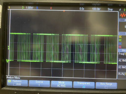
With this all turned on, we can see the output pin making step changes in output level. The frequency isn’t quite right (sine wave period is ~300 ms, ie ~3.3 Hz, but the code asked for 10 Hz), but it looks like a sine modulated PWM and we can fix the frequency later.