A simple inverter
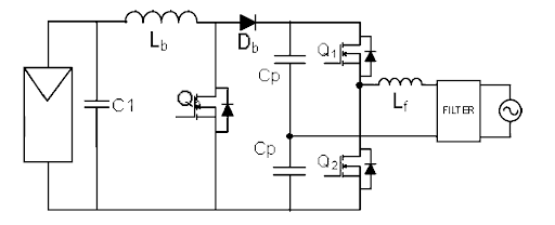
It’s possible to make an inverter with nothing more than a pair of caps and a half-bridge. Here’s a circuit:

In this schematic, borrowed from Meneses’s 2012 review, we see a boost stage (to bring the DC voltage up from module level) followed by a pair of capacitors wired in series in parallel with a half-bridge. In use, the voltage between the caps floats to the midpoint of the high and low voltage rails. We connect the load across the switching node of the half bridge and the midpoint of the capacitors. We use pulse-width modulation to control our desired output (normally a sine wave), and an inductor and line filter to clean up the output. This isn’t the only choice, nor even a particularly good choice, but it is fairly easy to understand, model, and build.

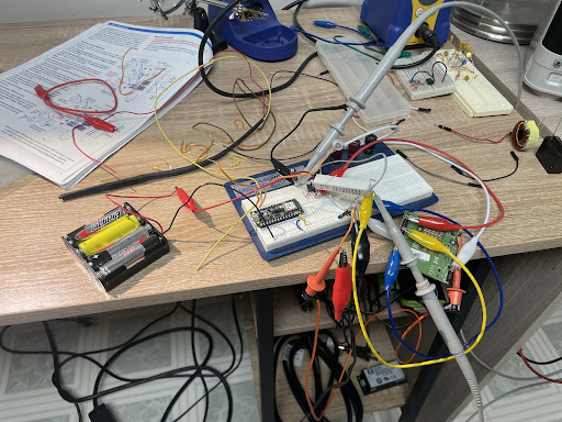
Here’s what it looks like on the bench, if you’re a caveman. For the half bridge I’ve wired in an EPC90121 dev board. No boost stage, just a few AA’s to give something to modulate. No output filter either.

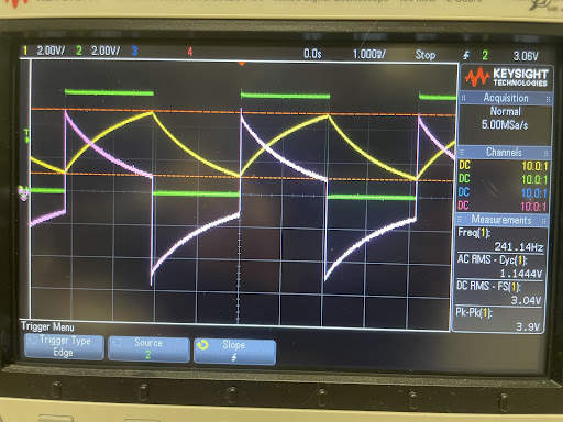
Attaching probes to each side of the load resistor lets us confirm that voltage and current is in fact flowing in both directions. So yes, it is inverting.