ADC front end
Now that we’ve tried out the onboard ADC, we need to talk about how to make it useful, ie how exactly to connect the signals of interest to the measurement input. We can’t just tie it directly, we’ll want to deal with signals up to hundreds of volts, and the analog input pins can’t take anything outside of 0 to Vdd=3.3V without frying. There are several cases to cover.
-
Unipolar signal, low voltage
We might have a signal which is known to be in the allowed range of the input pins. It seems like it’d work to connect this directly, and it kinda would, but it’d be usual to at least put a series resistor in line. 1 kohm, 10 kohm, something. This will help protect the pins from stray charges, and (with the ADC input capacitance) filter the signal somewhat. If we want more filtering, a cap to ground works. A filter corner near the sampling bandwidth works, to attenuate high frequency noise which will otherwise be aliased into our signal of interest. We’re going to have a lot of strong high frequency currents running around, we are building a switching power converter, so we shouldn’t be surprised if there’s crosstalk into signals we’re trying to measure.
-
Unipolar signal, high(er) voltage
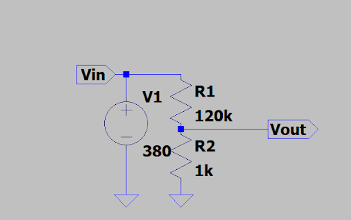
We also might have a signal which is known to be positive relative to chip ground, but at a higher voltage than the chip permits. This isn’t truly high voltage, per IEC and similar guidelines, which refers to voltages which can arc, typically > 1 kV. We’re never going to consider actual high voltage. Rather we’re talking about anything which might reach over 3.3V, or whatever voltage we’re driving the chip at. We can use resistor voltage divider can bring the signal into the allowed range. For instance, a 200 Vrms output might be generated from a DC link voltage of 315 V (assuming 90% duty cycle), and allowing a 20% headroom for measurement gives us a need to measure 380 V. To reduce a 380V range into a 3.3V range, the voltage divider needs a ratio of about 0.00868. We can add a cap to ground for antialias filtering.
-
Bipolar signal, high voltage
We will also need to work with bipolar signals, which are both positive and negative compared to ground. These will need to be level shifted. A natural way to do this is to use the same voltage divider, but against a midlevel voltage.
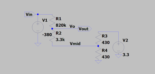
Here we just use another voltage divider to make the midlevel voltage. This isn’t great: there’s a continuous passive drain through R3 and R4, and also the midlevel voltage will shift somewhat as Vin goes to large positive and large negative values, injecting or withdrawing current through the R3-R4 divider. Using fairly big resistance in the R1-R2 divider and smallish in R3-R4 minimizes this, and it’s all linear anyway so can be calibrated out. 800 kOhms is a kindof big resistance, but not so large that it overwhelms the ability of an nRF52 analog pin to equilibrate in a reasonable time.
An associate pointed out that the R2-R3-R4 triad forms a wye connection, which can be converted to a delta connection with the wye-delta transform. The third leg of the delta is just a resistor from V2 to ground and can be deleted, removing most of the passive drain. Here’s what that looks like:
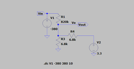
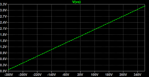
The Vout is 0 to 3.3V for Vin between -380 and 380, as desired.
This is not in fact a unique design. The same basic topology, with pull-up and pulldown resistors to the rails, can be seen for instance in the input stage of external ADCs, such as this taken from Analog Devices excellent Data Conversion Handbook:
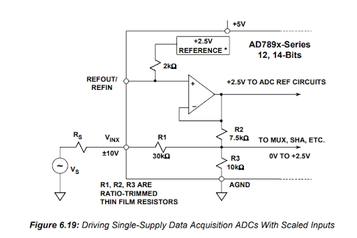
For high performance ADCs, high bandwidth and/or precision, particularly working with low impedance sources, the analog front end will be more complicated, usually involving active components like op-amps or instrumentation amplifiers.