Analog-digital conversion
To interact with the world, the inverter will need to be able to measure voltages and currents at its inputs and outputs, as well as internal state. This is the realm of analog-digital conversion. Because this need is so ubiquitous, many microcontrollers have some capability built-in. The nRF52840 has a successive approximation ADC peripheral, documentation here. Its specs are reasonable: 8 single ended channels, 200 ksps overall sample rate, 12 bit resolution (14 with oversampling), 9 bits effective after noise and distortion. Much fancier units exist, but this is already there, on the chip. Maybe it’ll be good enough.
Before going over how to use the ADC, let’s talk about what our requirements on accuracy are. For a microinverter, the authors of IEEE 1547 were kind of enough to figure out minimal requirements. These are at least an excellent starting point. Here are some of the requirements taken from Table 3 in IEEE 1547-2018 Section 4.4:
| Parameter | Minimum measurement accuracy | Measurement window | Range |
|---|---|---|---|
| Voltage RMS | ±1% Vnom | 10 cycles | 50-120% Vnom |
| Frequency | 10 mHz | 60 cycles | 50 - 66 Hz |
| Active power | ±5% rated power | 10 cycles | 20 - 100% rated |
| Reactive power | ±5% rated power | 10 cycles | 20 - 100% rated |
| Time | 1% of measured duration | N/A | 5 - 600 s |
There are separate, more relaxed specs for transient measurements. These look largely easy to achieve, with the possible exception of the 1% voltage measurement. Getting the noise down to that level isn’t bad, 1% is 7 bits, but the accuracy of the voltage reference now matters if we want our total error to be sub 1%. The nRF52840 allows use of an internal 0.6V reference, or using the chip’s VDD (usually 3.3V) as a reference. This chip does not support an external high precision reference, the way an external ADC would. The 0.6V reference has no electrical specification for its accuracy, but a Nordic engineer claimed it’s good to 0.2% at room temperature, and 2-3% over its full voltage and temperature range. The chip VDD voltage is whatever you give it. It’s not normally great to use as a reference, since the line is likely noisy and the output levels are not intended as a reference. But we can also use the 3.3V for measuring signals and measure the 3.3V with the 0.6V, ie calibrate. There are options.
So how do we use it? A reasonable sample to start with is zephyr/samples/drivers/adc (gh). What pins are connected to what matters. So we have to set that up.

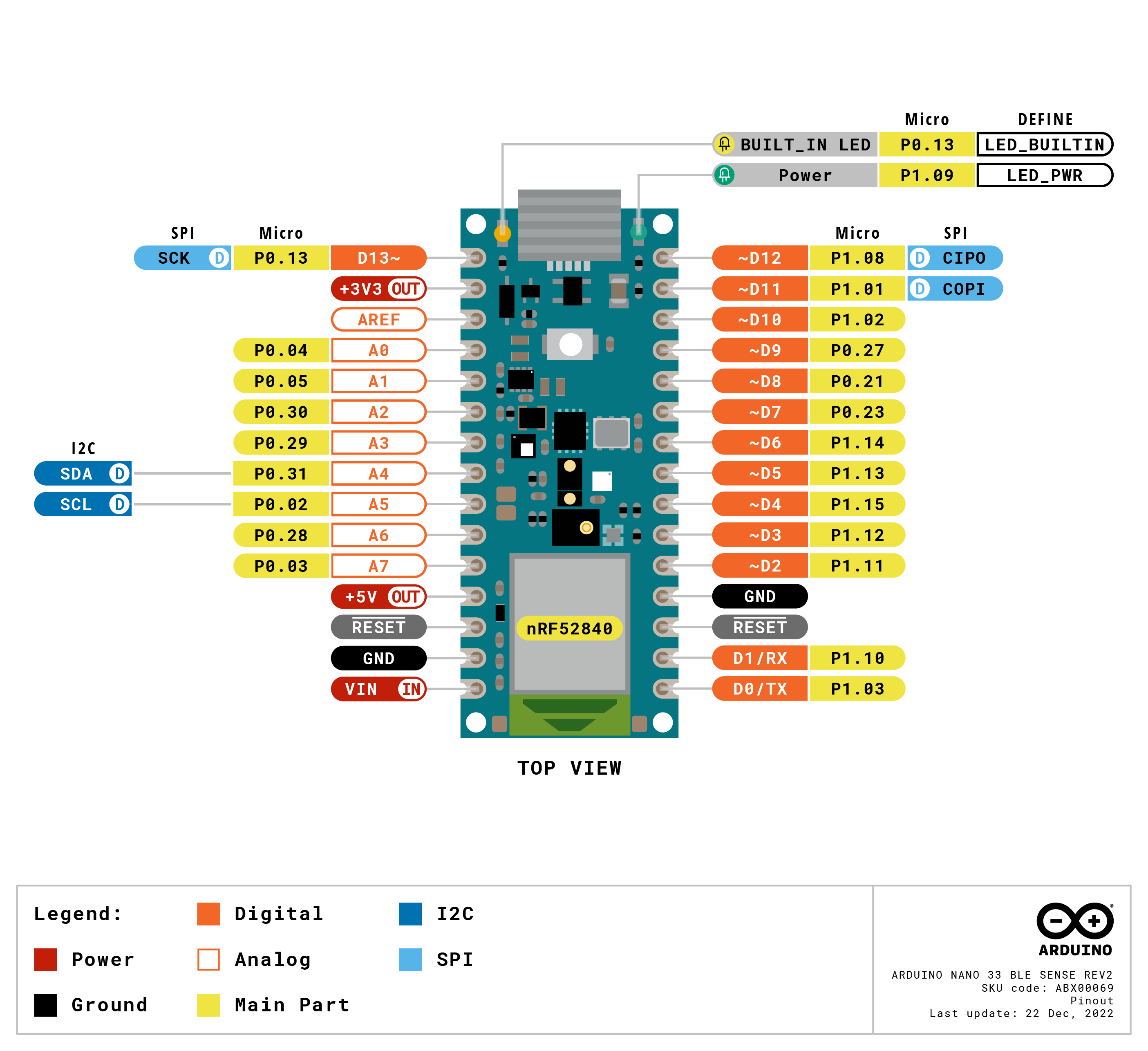
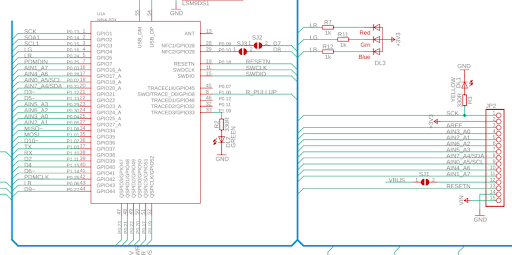
The Arduino Nano 33 BLE pinout has pins labelled A0-A7, but these are Arduino labellings, and while they are connected with the nRF’s analog pins, the numbers don’t match. The nRF naming AIN0-AIN7 can be found on the hard-to-find board schematic (below) and compared with the pin assignments on the nRF52840 PS.

Knowing what AINx connects to which header pin, we can write an overlay setting up the ADC.
/ {
	chosen {
		zephyr,console = &cdc_acm_uart0;
	};

	zephyr,user {
		io-channels = <&adc 0>, <&adc 7>;
	};
};

&zephyr_udc0 {
	cdc_acm_uart0: cdc_acm_uart0 {
		compatible = "zephyr,cdc-acm-uart";
	};
};

&adc {
	#address-cells = <1>;
	#size-cells = <0>;

	channel@0 {
		reg = <0>;
		zephyr,gain = "ADC_GAIN_1_6";
		zephyr,reference = "ADC_REF_INTERNAL";
		zephyr,acquisition-time = <ADC_ACQ_TIME_DEFAULT>;
		zephyr,input-positive = <NRF_SAADC_AIN1>; /* P0.03 */
		zephyr,resolution = <12>;
	};

	channel@7 {
		reg = <7>;
		zephyr,gain = "ADC_GAIN_1_6";
		zephyr,reference = "ADC_REF_INTERNAL";
		zephyr,acquisition-time = <ADC_ACQ_TIME_DEFAULT>;
		zephyr,input-positive = <NRF_SAADC_VDD>;
		zephyr,resolution = <12>;
	};
};
Two ADC channels are set up: 0, and 7; with ADC channel 0 hooked to AIN1, pin P0.03, A7 on the Arduino Nano header; and ADC channel 7 hooked to VDD. Both are configured with the same gain and using the 0.6V ref, and the default acquisition time (not sure what that is). We also have a couple things for setting up the console.
We also need a prj.conf:
CONFIG_ADC=y

CONFIG_USB_DEVICE_STACK=y
CONFIG_USB_DEVICE_PRODUCT="Zephyr USB console sample"
CONFIG_USB_DEVICE_PID=0x0004
CONFIG_USB_DEVICE_INITIALIZE_AT_BOOT=n

CONFIG_SERIAL=y
CONFIG_CONSOLE=y
CONFIG_UART_CONSOLE=y
CONFIG_UART_LINE_CTRL=y
This configures the ADC, and the console. Finally, main.c:
#include <inttypes.h>
#include <stddef.h>
#include <stdint.h>

#include <zephyr/device.h>
#include <zephyr/devicetree.h>
#include <zephyr/drivers/adc.h>
#include <zephyr/kernel.h>
#include <zephyr/sys/printk.h>
#include <zephyr/sys/util.h>

#include <zephyr/usb/usb_device.h>
#include <zephyr/drivers/uart.h>

BUILD_ASSERT(DT_NODE_HAS_COMPAT(DT_CHOSEN(zephyr_console), zephyr_cdc_acm_uart),
	     "Console device is not ACM CDC UART device");


#if !DT_NODE_EXISTS(DT_PATH(zephyr_user)) || \
	!DT_NODE_HAS_PROP(DT_PATH(zephyr_user), io_channels)
#error "No suitable devicetree overlay specified"
#endif

#define DT_SPEC_AND_COMMA(node_id, prop, idx) \
	ADC_DT_SPEC_GET_BY_IDX(node_id, idx),

/* Data of ADC io-channels specified in devicetree. */
static const struct adc_dt_spec adc_channels[] = {
	DT_FOREACH_PROP_ELEM(DT_PATH(zephyr_user), io_channels,
			     DT_SPEC_AND_COMMA)
};

int main(void)
{
	int err;
	uint32_t count = 0;
	uint16_t buf;

	const struct device *const dev = DEVICE_DT_GET(DT_CHOSEN(zephyr_console));
	uint32_t dtr = 0;

	if (usb_enable(NULL)) {
		return 0;
	}

	/* Poll if the DTR flag was set */
	while (!dtr) {
		uart_line_ctrl_get(dev, UART_LINE_CTRL_DTR, &dtr);
		/* Give CPU resources to low priority threads. */
		k_sleep(K_MSEC(100));
	}

	struct adc_sequence sequence = {
		.buffer = &buf,
		/* buffer size in bytes, not number of samples */
		.buffer_size = sizeof(buf),
	};

	/* Configure channels individually prior to sampling. */
	for (size_t i = 0U; i < ARRAY_SIZE(adc_channels); i++) {
		if (!device_is_ready(adc_channels[i].dev)) {
			printk("ADC controller device %s not ready\n", adc_channels[i].dev->name);
			return 0;
		}

		err = adc_channel_setup_dt(&adc_channels[i]);
		if (err < 0) {
			printk("Could not setup channel #%d (%d)\n", i, err);
			return 0;
		}
	}

	while (1) {
		printk("ADC reading[%u]:\n", count++);
		for (size_t i = 0U; i < ARRAY_SIZE(adc_channels); i++) {
			int32_t val_mv;

			printk("- %s, channel %d: ",
			       adc_channels[i].dev->name,
			       adc_channels[i].channel_id);

			(void)adc_sequence_init_dt(&adc_channels[i], &sequence);

			err = adc_read(adc_channels[i].dev, &sequence);
			if (err < 0) {
				printk("Could not read (%d)\n", err);
				continue;
			}

			/*
			 * If using differential mode, the 16 bit value
			 * in the ADC sample buffer should be a signed 2's
			 * complement value.
			 */
			if (adc_channels[i].channel_cfg.differential) {
				val_mv = (int32_t)((int16_t)buf);
			} else {
				val_mv = (int32_t)buf;
			}
			printk("%"PRId32, val_mv);
			err = adc_raw_to_millivolts_dt(&adc_channels[i],
						       &val_mv);
			/* conversion to mV may not be supported, skip if not */
			if (err < 0) {
				printk(" (value in mV not available)\n");
			} else {
				printk(" = %"PRId32" mV\n", val_mv);
			}
		}

		k_sleep(K_MSEC(1000));
	}
	return 0;
}
This combines the console setup, and the reading of the ADC is exactly as in the sample.
Connecting a 1.2V source to the A7 header pin, we get the following output:
ADC reading[12]:
- adc@40007000, channel 0: 1368 = 1202 mV
- adc@40007000, channel 7: 3726 = 3274 mV
ADC reading[13]:
- adc@40007000, channel 0: 1371 = 1204 mV
- adc@40007000, channel 7: 3725 = 3273 mV
ADC reading[14]:
- adc@40007000, channel 0: 1369 = 1203 mV
- adc@40007000, channel 7: 3733 = 3280 mV
ADC reading[15]:
- adc@40007000, channel 0: 1361 = 1196 mV
- adc@40007000, channel 7: 3724 = 3273 mV
ADC reading[16]:
- adc@40007000, channel 0: 1365 = 1199 mV
- adc@40007000, channel 7: 3728 = 3276 mV
ADC reading[17]:
- adc@40007000, channel 0: 1367 = 1201 mV
- adc@40007000, channel 7: 3728 = 3276 mV
ADC reading[18]:
- adc@40007000, channel 0: 1365 = 1199 mV
- adc@40007000, channel 7: 3732 = 3280 mV
ADC reading[19]:
- adc@40007000, channel 0: 1368 = 1202 mV
- adc@40007000, channel 7: 3711 = 3261 mV
ADC reading[20]:
- adc@40007000, channel 0: 1369 = 1203 mV
- adc@40007000, channel 7: 3736 = 3283 mV
ADC reading[21]:
- adc@40007000, channel 0: 1364 = 1198 mV
- adc@40007000, channel 7: 3730 = 3278 mV
ADC reading[22]:
- adc@40007000, channel 0: 1363 = 1197 mV
- adc@40007000, channel 7: 3719 = 3268 mV
ADC reading[23]:
- adc@40007000, channel 0: 1368 = 1202 mV
- adc@40007000, channel 7: 3715 = 3265 mV
ADC reading[24]:
- adc@40007000, channel 0: 1364 = 1198 mV
- adc@40007000, channel 7: 3721 = 3270 mV
ADC reading[25]:
- adc@40007000, channel 0: 1364 = 1198 mV
- adc@40007000, channel 7: 3718 = 3267 mV
Mean of channel 0 is 1200.14 mV, at the expected value to about 0.01%, with 1SD at 2.47 mV, or 0.2%. This shows that both my source and the 0.6V reference are in agreement to an absolute accuracy of 0.01%, which is honestly better than I would have expected for either the onboard 0.6V Vref or my external source. The noise shows we have 9 bits. A scope averaging the same line reads 1.2030V, so also about 0.2%. The VDD input shows a mean of 3273.14 mV, SD of 6.09 mV, so whatever LDO is on the Arduino board, it’s under the nominal 3.3V value by only about 1%. This is fine, better than I would have guessed. It’s not any noisier than the other channel, about 0.2% also. So the basic accuracy of this system looks adequate for our voltage sensing needs. Next, we’ll discuss scaling the inputs into a suitable range.