Toggling a pin
Suppose we want to control something, with a microcontroller. We need to create some type of output. Microcontrollers are set up so that you can use their pins for general purpose I/O. Here’s code which does that in the Arduino universe.
int togglePin = D9;

void setup() {
  pinMode(togglePin, OUTPUT);
}

void loop() {
  digitalWrite(togglePin, LOW);
  delay(3); // ms
  digitalWrite(togglePin, HIGH);
  delay(1);
}
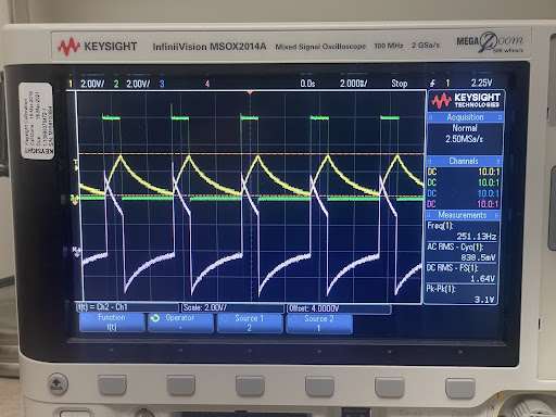
It sets up a single pin, labelled on the board as D9, which Arduino’s docs note is connected to P0.27, as a digital output. Then, in the main loop, it writes low and high values to the pin. On my Arduino, a Nano 33 BLE Sense, high is about 3.3 V and low is near zero.
We can use this to control a half-bridge, and get a kind of inverter.

It works, and wasn’t too hard to get going.
Due to reasons, the Arduino universe doesn’t really give access to all the features of the microcontroller that I think it’d be useful to have. This board uses the nRF52840 from Nordic Semiconductor, and Nordic provides their own stack, the NRF Connect SDK, based on the Zephyr RTOS. This is a complex, full featured system. But for any of it to be any use, I figured that I’d need to be able to toggle a pin.
The first step is being able to compile and run a program. Y’know, the “hello world” task. Compiling is not too bad. Nordic has a VSCode extension, with a large number of examples, and decent documentation. It’s mostly set up for Nordic’s own dev boards, but there is an arduino_nano_33_ble_sense board you can select as a build target. I started with the “blinky” example, which compiles out of the box.
Getting the compiled program flashed onto the board is not entirely trivial, though Arduino makes it look easy. There are a few options including wiring up SWD and using an external programmer, etc. What’s working for me today is bossac, the programming utility used by Arduino, and the bootloader on the Arduino itself. To use this, first have the Arduino environment installed, do a build inside VSCode, then use nRF’s Toolchain Manager to launch a bash window (from dropdown next to nRF Connect SDK version), cd to the directory of the application, double-click the board reset button to set the bootloader into a mode for receiving the binary (slow pulsing orange LED) then run west flash with Arduino’s bossac path as an option:
west flash --bossac=/c/Users/17802/AppData/Local/Arduino15/packages/arduino/tools/bossac/1.9.1-arduino2/bossac.exe --bossac-port=COM3
The COM port will depend on your board, and won’t be the same port it uses normally. The bossac path can be determined by setting your Arduino IDE preferences to verbose output during compile and upload then compiling and running a sketch. This is all a little awkward but it does work. (Procedure taken from Zephyr docs for Arduino Nano 33 BLE.)
Next up is to modify blinky to also toggle one of the external pins. This should be trivial, like the Arduino example above. It is more complex in the nRF world. The principal issue is devicetree which I think is supposed to allow Zephyr to support any hardware with static configuration in a very general fashion. Nordic does have a number of examples, but they all deal with Nordic boards and do not require modifying the devicetree. I eventually found success from here. Full code.
First, is to basically copy the blinky code with similar lines for our custom GPIO pin, P0.27 labelled as D9. We pretend we can access it with a devicetree alias, just as the LED got accessed with the devicetree alias led0.
#include <zephyr/kernel.h>
#include <zephyr/drivers/gpio.h>


#define SLEEP_TIME_MS   2

#define LED0_NODE DT_ALIAS(led0)

static const struct gpio_dt_spec led = GPIO_DT_SPEC_GET(LED0_NODE, gpios);

#define CUSTOMGPIO_NODE DT_ALIAS(mycustomgpio)
static const struct gpio_dt_spec customgpio = GPIO_DT_SPEC_GET(CUSTOMGPIO_NODE, gpios);

void main(void)
{
	int ret;

	if (!device_is_ready(led.port)) {
		return;
	}

	ret = gpio_pin_configure_dt(&led, GPIO_OUTPUT_ACTIVE);
	if (ret < 0) {
		return;
	}

	if (!device_is_ready(customgpio.port)) {
		return;
	}

	ret = gpio_pin_configure_dt(&customgpio, GPIO_OUTPUT_ACTIVE);
	if (ret < 0) {
		return;
	}


	while (1) {
		ret = gpio_pin_toggle_dt(&led);
		if (ret < 0) {
			return;
		}
		ret = gpio_pin_toggle_dt(&customgpio);
		if (ret < 0) {
			return;
		}

		k_msleep(SLEEP_TIME_MS);
	}
}
This won’t compile, obviously, without something else, because the new alias mycustomgpio doesn’t exist. We have to modify the devicetree to mention it, and tell the system what that alias should be connected to. We do this by adding an overlay file in the project root, named after the board. So here is arduino_nano_33_ble_sense.overlay:
/{
	custom_leds {
 	   compatible = "gpio-leds";
	   customgpio: customgpio_0 {
		  gpios = <&gpio0 27 GPIO_ACTIVE_HIGH>;
		  label = "My custom GPIO";
	   };
	};
	aliases {
		mycustomgpio = &customgpio;
	};
 };
I’m not entirely certain what parts of this are strictly required. But it does set up a node customgpio which is the 27th pin of the processor’s GPIO0.
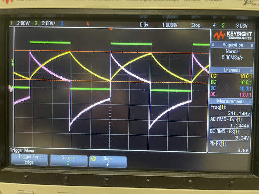
And, stuffed into the inverter circuit, it behaves about the same as the Arduino version. (Slighly different duty cycle.)

Update:
The overlay file above has lots of reference to LEDs even though the pin I want to toggle, and direct reference to GPIO0.27 even though there’s an Arduino Nano header defined as part of the board in Zephyr. Here’s a cleaned up version. It still uses gpio-leds as the compatible property, which is basically serving as a generic output binding. The discussion here is more or less in accordance.
/{
	customgpios {
		compatible = "gpio-leds";
		customgpio: customgpio_0 {
			gpios = <&arduino_nano_header 9 GPIO_ACTIVE_HIGH>;
		};

	};
	aliases {
		mycustomgpio = &customgpio;
	};
};